
تستر قطعات الکترونیکی مدل GM328A
-پس از خرید محصولات دانلودی و آموزشی به صفحه ی پروفایل قسمت دانلود ها مراجعه و فایلهای خود را دانلود کنید.
-زمان ارسال 3 تا 7 روز کاری
محصولات مشابه
توضیحات بیشتر
تستر قطعات الکترونیکی مدل GM328A یک ابزار چندکاره و دقیق برای شناسایی و بررسی انواع قطعات الکترونیکی است. این دستگاه با قابلیت شناسایی خودکار قطعات مانند ترانزیستورها، دیودها، مقاومتها، خازنها، سلفها و MOSFETها طراحی شده است. صفحهنمایش LCD رنگی آن اطلاعات کاملی از مشخصات قطعات مانند مقاومت داخلی، ظرفیت خازن، و نوع نیمههادی را نمایش میدهد. این تستر برای تعمیرات، آموزش، و پروژههای الکترونیکی بسیار کاربردی است و میتواند انواع قطعات را با سرعت و دقت بالا تست کند.
تستر قطعات الکترونیکی مدل GM328A یکی از پیشرفتهترین ابزارها برای شناسایی و تحلیل انواع قطعات الکترونیکی است. این دستگاه با امکانات بینظیر خود قادر به شناسایی ترانزیستورها، دیودها، مقاومتها، خازنها، MOSFETها، تریستورها و بسیاری قطعات دیگر است. این تستر مجهز به یک صفحهنمایش رنگی 2.4 اینچی است که اطلاعات کاملی از قطعه مورد تست، از جمله مشخصات پایهها، ظرفیت، مقاومت داخلی و نوع نیمههادی نمایش میدهد. دستگاه قابلیت تولید موج PWM و اندازهگیری فرکانس را نیز دارد.
مشخصات فنی تستر قطعات الکترونیکی مدل GM328A
ولتاژ ورودی: 6.8 ولت تا 12 ولت DC
ولتاژ کاری: حدود 30 میلیآمپر (در ولتاژ 7.5 ولت)
صفحهنمایش: رنگی 2.4 اینچی با رزولوشن 160×128
تست قطعات: ترانزیستورها (PNP/NPN)، دیودها، مقاومتها، خازنها، سلفها، MOSFETها، TRIAC، و تریستورها
محدوده اندازهگیری:
خازنها: 25 پیکوفاراد تا 50 میلیفاراد (برای ظرفیت بالاتر است 1 میلی فاراد، باید با مقاومت کوچک مثل 56 اهم سری شوند)
مقاومتها: 0.1 اهم تا 50 مگااهم
ویژگیهای اضافی: تولید موج PWM، اندازهگیری فرکانس تا 1 مگاهرتز، اندازهگیری ESR خازنها
ابعاد: 90x70x20 میلیمتر
کاربردهای تستر قطعات الکترونیکی مدل GM328A
تعمیر و عیبیابی قطعات الکترونیکی
آموزش و یادگیری مدارهای الکترونیکی
طراحی و توسعه سیستمهای الکترونیکی
استفاده در آزمایشگاهها و کارگاههای تخصصی
نحوه استفاده از تستر قطعات GM328A
این تستر از طریق یک دکمه چرخان چندمنظوره کنترل میشود که ۶ عملکرد اصلی دارد: فشار کوتاه، فشار بلند، چرخش به چپ، چرخش به راست، چرخش مداوم به چپ، و چرخش مداوم به راست.
روشن کردن و آغاز تست:
در حالت خاموش، با یک فشار کوتاه دکمه، دستگاه روشن شده و فرآیند تست آغاز میشود.
اگر دستگاه قطعهای را شناسایی نکند، با یک فشار بلند یا چرخاندن دکمه میتوانید به منوی عملکردها وارد شوید.
انتخاب عملکردها:
در منوی عملکردها، با چرخاندن دکمه به سمت چپ یا راست میتوانید بین آیتمهای منو جابجا شوید.
برای انتخاب یک عملکرد، کافی است یک بار دکمه را به صورت سریع فشار دهید.
برای خروج از عملکرد انتخاب شده، دکمه را به مدت طولانی فشار دهید.
توزیع نقاط تست:
دستگاه دارای سه نقطه تست (TP1، TP2، TP3) است که روی پایه تست و قسمت مشخصی برای قطعات SMD قرار دارند.
در هنگام تست قطعات دو پایه، هر دو پایه میتوانند به طور دلخواه به TP1 و TP3 متصل شوند.
برای قطعات سهپایه، هر پایه باید به نقطه تست مشخص متصل شود.
نحوه تست خازنها:
پیش از تست خازنها، مطمئن شوید که آنها کاملاً دشارژ شده و به درستی در سوکت تست قرار گرفتهاند.
تستر بهطور خودکار مقادیر ظرفیت و مقاومت داخلی (ESR) خازن را نمایش میدهد.
کالیبراسیون دستگاه:
کالیبراسیون به دو روش انجام میشود:
کالیبراسیون سریع:
سه نقطه تست (TP1، TP2، TP3) را با استفاده از سیم کوتاه کنید.
دکمه تست را فشار دهید تا پیام “Selftest mode ..?” ظاهر شود و سپس دوباره دکمه را فشار دهید.
پس از پایان پیامها، سیمها را جدا کنید.
کالیبراسیون کامل:
وارد منوی عملکردها شوید و گزینه “Selftest” را انتخاب کنید.
سه نقطه تست را کوتاه کنید و سپس سیمها را جدا کنید.
خازن 220 نانوفاراد را به TP1 و TP3 متصل کنید و منتظر پایان فرآیند کالیبراسیون بمانید.
عملکردهای ویژه:
اندازهگیری فرکانس: اندازهگیری فرکانس از 1Hz تا 1MHz. برای خروج، دکمه را طولانی فشار دهید.
تولید موج PWM: قابلیت تنظیم دامنه پالس از 1% تا 99%.
اندازهگیری مقاومت و اندوکتانس: بهطور پیوسته مقاومت زیر 2100 اهم و اندوکتانس 0.01 میلیهانری تا 20 هانری را نمایش میدهد.
این مراحل به شما کمک میکنند تا از تمامی قابلیتهای این تستر پیشرفته به بهترین شکل بهرهبرداری کنید.
اطلاعات بیشتر در مورد تستر قطعات الکترونیکی مدل GM328A
دفترچه راهنمای راه اندازی
معرفی جزئی محصول
Input Voltage: DC 6.8V-12V
Operating voltage: approximately 30mA, as measured with a 7.5V DC input
How to use GM328A Component Tester
The tester is operated using a rotary encoder switch.
The rotary encoder switch offers 6 functions: short press, long press, left rotation, right rotation, continuous left rotation, and continuous right rotation.
While in shutdown mode, a single short press powers on the device and initiates testing.
Upon completion of the test without detecting a device, a long press of the switch or left/right rotation enters the function menu.
Within the function menu, use the left or right rotary switch to navigate up and down through menu items.
To select a function item, quickly press the switch once.
For exiting a function, press and hold the switch.
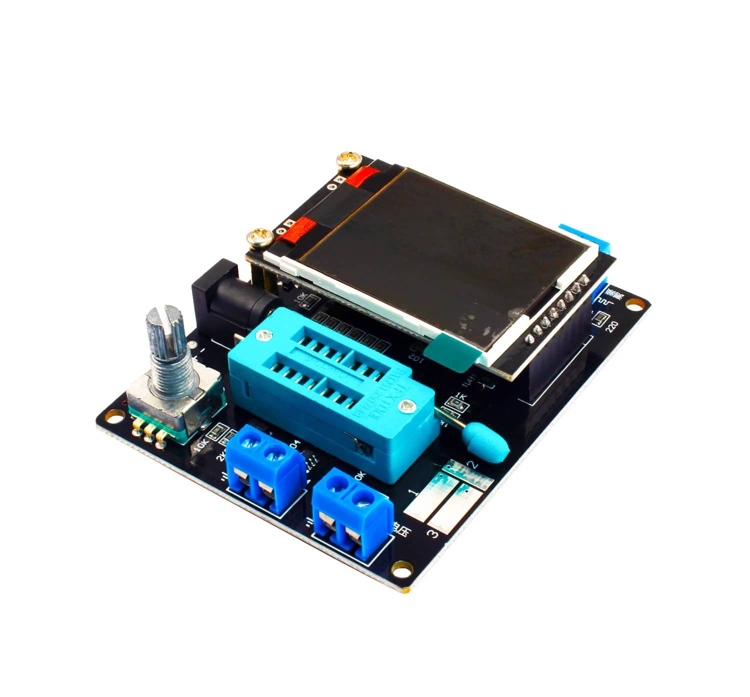
GM328A Component Tester on-board components review
Control button
Square wave and PWM output
Voltage measurement interface
Original test bit
On the original test base
160 × 128 color display
Frequency messurement interface
Power adapter socket
9V battery contact 9V
Test the GM328A Component Tester
The tester has 3 test points, TP1, TP2, TP3. The distribution of these three test points in the test block is as follows:
Next to the testing seat is the patch component test area, labeled with numbers 1, 2, and 3, corresponding to TP1, TP2, and TP3 respectively.
When testing a component with only 2 pins, the test order of the pins is not specified. Any 2 pins can be selected for testing at TP1 and TP3. For a 3-pin component, each pin is tested at its respective TP regardless of order. After testing, the tester automatically identifies and displays the pin names and test points on the screen.
For components with only 2 pins, using TP1 and TP3 will automatically switch to continuous test mode after testing, allowing synchronous measurement without needing to press the switch again. Testing with “TP1 and TP2” or “TP2 and TP3” only requires one test. Press the switch once to re-test.
Before testing capacitors, ensure they are discharged and correctly inserted into the test socket to prevent damage to the tester’s microcontroller.
Calibration of GM328A Component Tester
Tester calibration serves to eliminate errors in your components and enhance the accuracy of final test results. Calibration is categorized into quick calibration and full function calibration.
For quick calibration, follow these steps: Short-circuit the three test points TP1, TP2, and TP3 using wires, then press the test button while monitoring the screen. The screen will switch to black and white. Once “Selftest mode ..?” appears, press the test button again to initiate quick calibration. If there’s no button press within 2 seconds, the normal test process resumes, displaying resistance values for TP1, TP2, and TP3. Ignore any additional data on the screen until a flashing message appears.
After isolating the probes, remove the short-circuit wires from TP1, TP2, and TP3. The screen will display “Test End” when quick calibration is complete. Use full function calibration initially for more comprehensive calibration.
Full function calibration requires entering the function menu and using a 220nf capacitor. This method offers a detailed calibration process and takes longer. Navigate to the “Selftest” menu item in the function menu, turn the test knob accordingly, and press the test button to begin full calibration. The screen will flash “short probes!”—repeat the short-circuiting of TP1, TP2, and TP3 with wires. When “Isolate Probes!” flashes, remove the wires from the test points and wait for further prompts.
Upon seeing “1-||-3>100nf”, place the 220nf capacitors on TP1 and TP3 as prepared. Once “Test End” appears on the screen, the full function calibration process concludes.
Function menus of GM328A Component Tester
Frequency Measurement: To measure frequency, long-press the test button to exit this function. Frequency measurement ranges from 1Hz to above 1MHz. Frequencies below 25KHz display the period.
f-Generator: This is a square wave generator offering various frequencies. Rotate the test knob left or right to switch frequencies and press the test button to exit.
10-bit PWM: Adjust pulse duty cycle from 1% to 99% using the left or right test knob. Long-press the test button to exit the pulse signal generator.
C + ESR @ TP1:3: Online capacitance measurement function using TP1 and TP3. Measure capacitance (2uF-50mF) and ESR. Ensure capacitors are discharged and circuits disconnected before testing.
Continuous Measurement: Continuously measures resistance and inductance at TP1 and TP3. Resistance measured is less than 2100 ohms, and inductance ranges from 0.01 mH to 20H. Long-press the test button to exit.
-||-3: Continuously measures capacitance at TP1 and TP3. Essential for small capacitors. Measures ESR for capacitors above 90nF with a resolution of 0.01Ω. Capacitors over 5000pF display voltage drop rate after charging.
S18B20 (Russian version does not support this function): DS18B20 is a temperature sensor using single-bus communication. It is packaged similarly to a triode (TO-92). Pin distribution is shown below.
Upon adding the DS18B20 test function, the second line of the display indicates the connection between the test socket and DS18B20 as “1 = GND 2 = DQ 3 = VDD”. This specifies that TP1 connects to DS18B20 ground, TP2 to DS18B20 DQ, and TP3 to DS18B20 VDD. The tester does not automatically detect DS18B20, so it is essential to follow these instructions for proper installation.
Once installed, the tester can read the DS18B20’s 12-digit temperature data and display the corresponding Celsius temperature on the third line, accurate to 0.0625°C resolution.
Scratchpad: This includes the contents of the 8 storage registers inside the DS18B20, along with the CRC check value of the last byte, totaling 9 bytes.
دیدگاهها افزودن نظر
چند مورد از قابلیتهای انحصاری این مدل را ذکر میکنم :
- نمایشگر بزرگ رنگی TFT با امکان شخصی سازیِ رنگِ فونتها و بَـک گرآوند.
- قابلیت تستِ دقیقترِ قطعات با انتخابِ آن قطعهی خاص از داخل منو ( مثلن در سایر تسترها اگر اندوکتانسِ سلفِ موردِ تست پایین باشد، تستر آن را مقاومت یا اتصال کوتاه تشخیص میدهد، اما در این مدل از لیست منو میتوان گزینه سلف را انتخاب کرده و مقدار اندوکتانس را مشاهده کرد ).
- امکان اندازهگیری ولتاژ DC تا پنجاه ولت.
- امکان اندازهگیری فرکانس موج مربعی.
- سیگنال ژنراتور موج مربعی و تغییر Duty Cycle .
- اندازه گیری دقیقِ دما و رطوبت با قرار دادن سنسور DHT11 در زیف سوکت.
- اندازهگیری دما با قرار دادن سنسور DS1820 .
- تست گیرنده های IR سه پایه و تست سلامت ریموت کنترلهای خانگی.
تنها موردی که آن هم فقط در مدل LCR-T7 وجود دارد و در این مدل وجود ندارد تست دیود Zener و مشاهده ولتاژ شکست آن است. البته در مدل LCR-T7 فقط دیودهای زینر حداکثر تا ۲۸ ولت امکان تست دارند. چون برای مشاهده ولتاژ شکست یک دیود زینر به ولتاژی حداقل برابر با ولتاژ دیود زینر نیاز داریم. در مدل LCR-T7 این ولتاژ توسط آی سی افزاینده MT3608 تأمین شده که ولتاژ ۴.۲ ولت باطری شارژی داخلش را به ۲۸ ولت بوست میکند. بنظر میآید علت حذف تست دیود های زینر در این مدل تستر این باشد که چون آی سی MT3608 یک افزاینده سوئچینگ است و فرکانس تولید شده از آن بر روی قابلیتِ سیگنال ژنراتور و اندازهگیری فرکانسِ این تستر تأثیر منفی میگذارد.
در ضمن در بخش کالیبراسیون به وضوح ذکر میکند که برای اتمام کالیبراسیون از یک خازن 100 نانو فاراد استفاده شود. استفاده از خازن ۲۲۰ نانو فاراد برای کالیبراسیون که در توضیحات ذکر کردهاید احتمال دارد از دقتِ آن بکاهد.
نکته مهم ابتدا برای کالیبره کردن این تستر باید روی سوکت زیف پایه های 1 و 2 و 3 با یک تکه سیم بهم وصل کنین و دستگاه روشن کنین
وقتی پیام اومد این سیم جدا کنین
البته باید کلید اصلی دستگاه 3 ثانیه نگه دارید
بعدش پیام میده که یک خازن 100 پیکو فاراد بین پایه 1 و 3 بذارید تا کالیبره تکمیل بشه
بعد آماده استفاده هست